Working with the VVT on a 4AGE 20V Engine
When Toyota went to the 20 valve engine from the 16V it introduced the first form of Variable valve timing (VVT) for any A series engine. It is the most simple form of variable valve timing in that it is not only on just the intake cam but it works only on two preset positions. Using oil pressure the cam belt pulley is either in a neutral position relative to the intake camshaft or in an advanced position. This is achieved by the use of an external oil control solenoid, dedicated oil gallery, an additional cam oiling slot & hole in the camshaft and of course the VVT pulley itself.
The VVT solenoid is located on the exhaust side of the head at the front. It has a constant positive on one terminal and the other is grounded by the ECU to activate the oil flow. The VVT solenoids are identical between the black and silvertops although in the blacktop it uses a variety of inputs such as engine load, temp ,etc.. to determine the VVT change over point. The actual VVT pulleys on the other hand are not interchangeable as they have a different offset starting position.
This is a 20V engine with the cam-belt cover removed. Visible is the left hand side pulley which is the VVT gear. The VVT solenoid is also visible as the cylindrical part facing outwards on the right hand side (exhaust side) of the engine. The two pin connector is unplugged and on the end of the solenoid facing upwards.
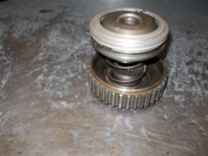
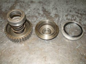
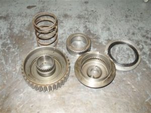
VVT GEAR INTERNALS
These pictures are of a VVT gear that have been disassembled. The work performed and photos are from Merv McCallum , Victoria, Australia. A big thanks to Merv for the permission to keep using these interesting photos.
VVT CHECKS AND TROUBLESHOOTING
Under normal conditions the VVT solenoid is normally activated from 2000 revs up to either 4500 with the original ECU or approximately 6000 with a new tune. Here are three ways to check the operation of the VVT:
– The easiest way to see if there is an issue is to simply drive with and without it being disabled. Simply unclip the plug from the VVT solenoid and perform a test drive. Without the VVT operational there should be a significant loss in the mid range power. If there isn’t a noticeable loss then it’s highly likely that the VVT pulley is no longer functional and needs replacement.
– As above but on a dyno and a power run with and without the solenoid connected. There should be a significant dip in mid range of the power curve between the VVT enabled and disabled dyno run.
– One side of the VVT solenoid has a constant positive power source, so by shorting out the second wire it will ground the cable and activate the solenoid. If the engine smoothness or idle revs don’t change then there is a fault in the system. The solenoid can be removed and have 12 volts directly connected to the terminals to see if it’s mechanically functioning. This however will very likely be a futile effort as these solenoids have proven to be highly reliable.
Below is a video of a person checking a VVT solenoid by applying power directly:
KNOWN FAILURES
It is the normal for age to have caught up with the original VVT pulleys and them to have either already failed or in the process of doing so. Therefore it’s suggested that all people with a used 20V engine to test it. A failed pulled if commonly characterised by having a loud clicking sound akin to a loose rocker arm. This has been nicknamed by some 20V owners as the “click of death”. Unfortunately this pulley is a non serviceable part and can’t be opened without cutting into them with something like a grinder. These are available new and genuine from us, see at the bottom of this page for their location on this site.
The other known failure has been reported by “Mr Acoustic” and is the power transistor in the ECU itself that does the power switching for the solenoid power return. This has been extensively covered on his website listed below:
REMOVING VVT
Having VVT in place means that the intake cam is not readily adjustable via a system like those on adjustable cam gears. The VVT pulley can be removed by using something along the lines of Toda’s “VVT canceling gear” which is an adjustable cam gear that suits the shape of the 20v cam but is just a normal adjustable cam gear. The second option is a much simpler and cheaper one; some aftermarket cam gears are shaped such that they suit a normal 16V intake gear and hence any readily available/home made adjustable gear can be used.
Note: Other than the exception above an adjustable pulley from a 4age 16V can be used but only on the exhaust side of the engine. It will however end up being one tooth out so the pulley should have a new mark put on it where required to avoid the belt being fitted incorrectly.
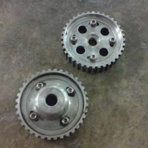
These two gears are made by Toda Japan for the 20V engine. It can be seen in the middle of the bottom gear how the center has been made so its raised to suit the shape of the 20V camshaft.
AFTERMARKET ECU CONTROL
How the VVT is controlled is determined by the options of the ECU in its auxiliary controls. If the aftermarket ECU in question has the option of turning an output on/off at a set revs and then the reverse later then a single relay can be used. The relay would ground the second side of the VVT solenoid and would be triggered directly.
For an ECU that can only switch the output once at a certain set revs then two outputs are needed. Each of the outputs would turn on a relay each, where the first relay would activate the VVT solenoid and the second cut the power to the first.
AFTERMARKET CAMS AND VVT
There is much speculation on what does and does not work with aftermarket cams and VVT control. Some report beyond a certain duration the pulleys retard the timing too much, citing things such as valves touching pistons from the extra ignition advance. The only cams on the market that are proven to be a drop in replacement using both of the original pulleys is the “Poncam” from Tomei. This product is known to work well with gains across the rev range and works on completely original engines.
TUNING
To determine the right points to turn the VVT solenoid on and off two dyno runs are needed; one with the solenoid locked on and vice-versa. The with both power charts overlapped on top of each other the highest peaks are chosen of each of the two curves. As a guide the VVT will be turned on early in the rev range off at approximately 6000RPM. These figures are almost always different between engines due to their different combination of parts.
RELATED PRODUCTS
4age 20V- elimination blanking plug: Suits all 20V engines
4age 20V Silvertop – VVT pulley
4age 20V Blacktop – VVT pulley
4age 20V – VVT solenoid: Suits all 20V engines
4age 20V – VVT solenoid plug / connector kit: Suits all 20V engines